Optical comparators are measurement systems that offer extremely accurate and repeatable measurement data. They use video images, geometric dimensioning and tolerance (GD&T),light, lenses, mirrors, and cameras to examine the tolerances of parts, assemblies, and components. Optical comparators are a valuable tool used by quality control inspection teams to determine the effectiveness of production methods and the quality of manufactured items.
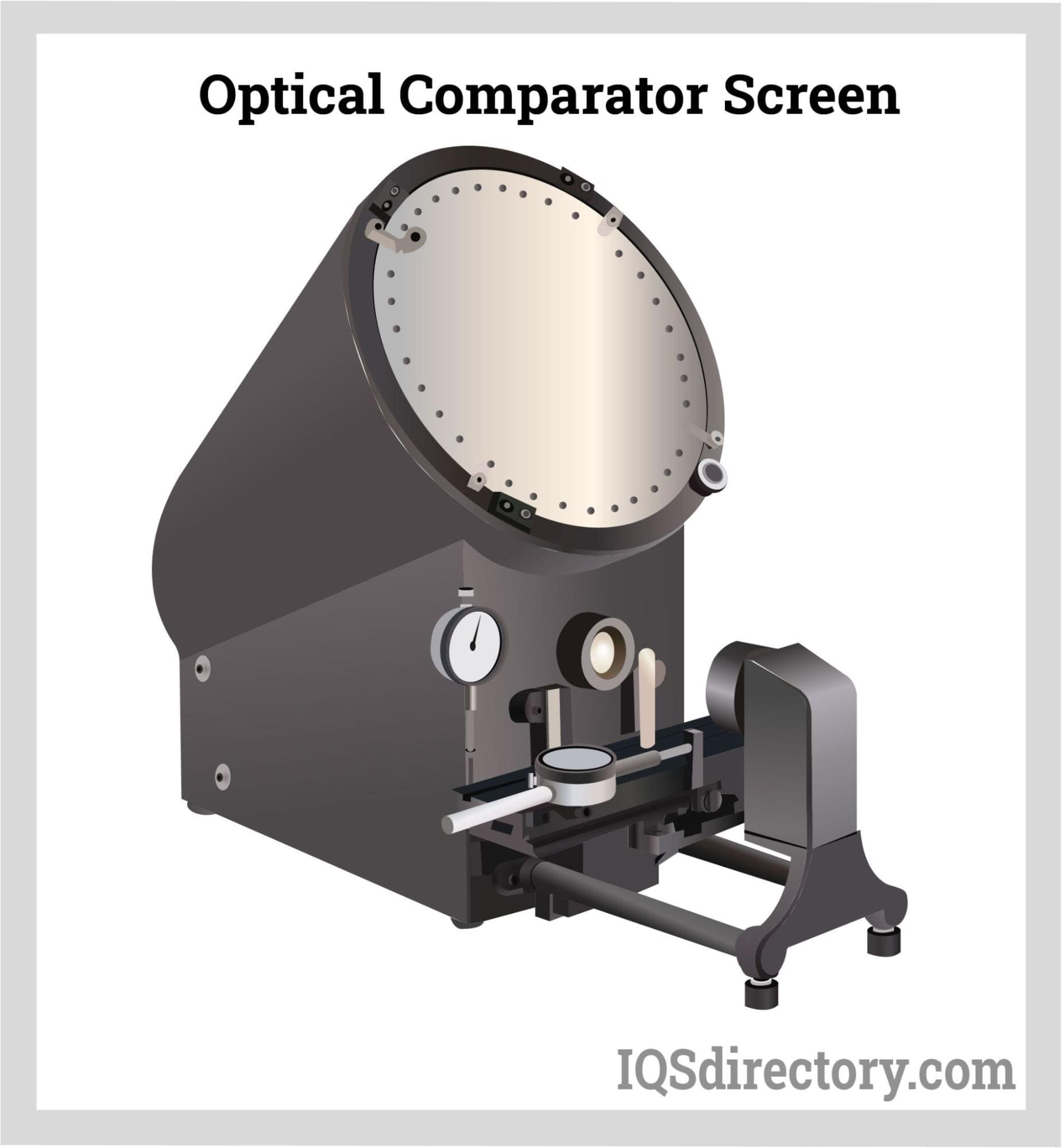
In the examination of a workpiece, an optical comparator projects the image of the workpiece onto a display screen where it is compared to the standard parameters of the workpiece. Complex stampings, gears, cams, threads, and other components are compared to their model. It is used for producing precision machinery for the aviation, aerospace, watch and clock industries, electronics, the instrumentation business, research facilities, and detection metering stations at all levels.
Flaws, scratches, indentations, and dimensional inaccuracies are immediately highlighted by the comparator, which is calibrated using the standard parameters of the workpiece.
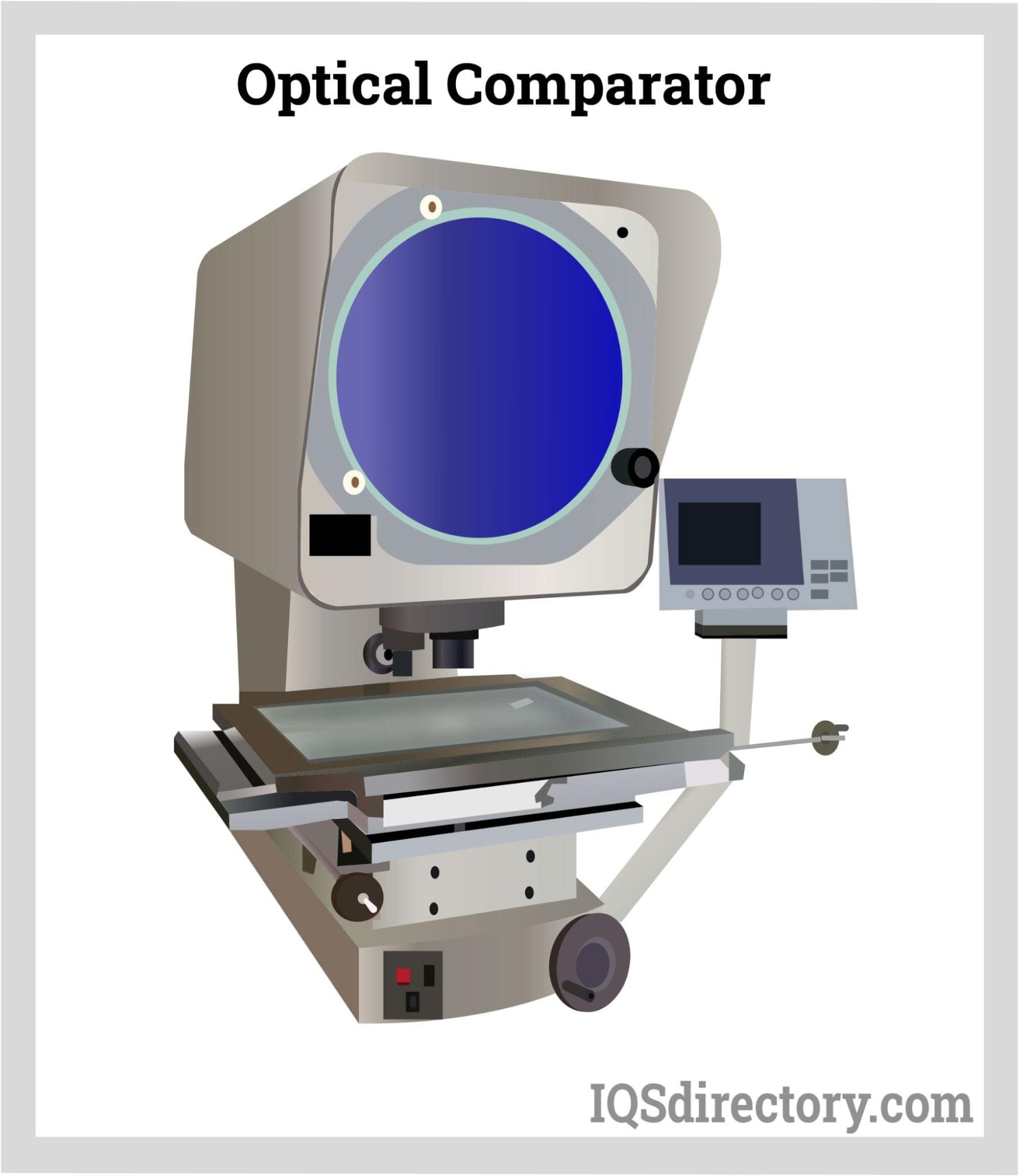
Optical Comparator Methods
Traditional Comparator Method
The first comparator was introduced in the 1920s and has changed very little since its introduction. Technologies, calibration methods, digital and software enhancements, and magnification have been added to improve and increase accuracy. In the traditional method, the workpiece is placed on a stage that is illuminated by light that comes from below the stage. A shadow of the workpiece is projected, through a lens and mirrors, onto a screen.
The image that is projected is magnified using a telecentric optical system to project the workpiece with accurate magnification. The telecentric lens projects the workpiece at the correct magnification without warping the image. The dimensional accuracy and surface defects of the projected image are compared to the parameters for the workpiece.
The primary configurations of comparators are horizontal and vertical where a horizontal comparator has a side view of the workpiece while the vertical view looks down on the workpiece. Horizontal and vertical optical comparators have been used for years by manufacturers as a means for determining product and part quality.
Regardless of their many years of use, traditional optical comparators have disadvantages especially in regard to the complexities of modern manufacturing.
- Complexity – Modern components are complex and intricate and must be observed from multiple angles using 3D projection systems.
- Accuracy – The reason for the use of comparators is to increase the accuracy of the inspection process that could not be achieved using hand measurements. Advancements in technology require that modern parts be capable of meeting the tightest and most demanding tolerances that cannot be achieved with a 2D projection system.
- Efficiency – Traditional optical comparators can measure one part at a time, which is a problem when thousands of parts are being produced.
- 2D – The optical comparators that have been used for many years are capable of projecting only 2D images, which is a problem when components have multiple dimensions.
Types of Optical Systems
Simple optics, corrected optics, fully corrected optics, and telecentric optic systems are the four basic categories of optical systems utilized in optical comparators.
- Simple Optics: A light source, a lens for magnification, a mirror for reflection, and a projection screen are the only components of the basic optics system. Simple optics will show a picture that is upside-down and reversed.
- Corrected Optics: By adding a second internal mirror to the simple optics system, the corrected optics system creates an upside-down and reversed image.
- Fully Corrected Optics: A final projected image of the part that is both right-side-up and unreversed is produced by an optical system that has been fully corrected. Any of these methods will work fine to finish measurement on an optical comparator. Still, the more sophisticated a system one employs, the easier it will be to convert the taken measurement back to the part’s equivalent measurement.
- Telecentric Optical Systems: Optical comparators can also utilize a telecentric optical system, which enables accurate magnification projection from any location on the stage. Using a general lens, one can assess perspective by making close items appear huge and far away ones appear small. Contrarily, telecentric lenses produce images of the same size for both nearby and distant objects. With this telecentric lens, one can cast an object’s shadow at the proper magnification without distorting the image.
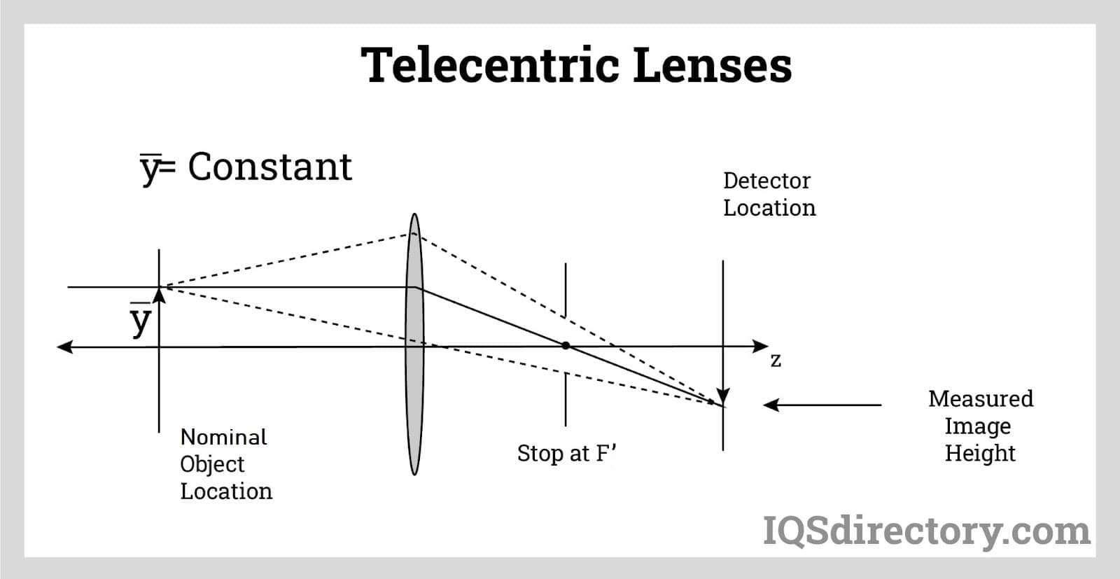
With a telecentric lens, the workpiece is aligned to be examined with a grid on the screen with measurements for distances to other points made from the projection. Additionally, the profile projector may have episcopic lighting (light shining from above), which illuminates internal areas.
The traditional manual method for comparators is rapidly being replaced by technologically advanced computer software. The three methods commonly used by manufacturers include:
- Software Evaluation: Digital video comparators, which are the forefront of the comparator industry, uses an electronic overlay of a CAD rendering or model of the workpiece to project a tolerance band onto the comparator screen. The software automatically changes, updates, and adjusts as the magnification changes. Comparator software reduces the time to enhance, calibrate, compare, and analyse the tolerances of a part or workpiece.
- Size of the Silhouette: This long used method for analysing a workpiece projects a silhouette of the workpiece onto a screen, which is used to calculate measurements. Moving the stage on which the part is mounted causes various spots on the silhouette to line up with the reticle at the screen’s center, one after another. A digital readout shows how far the stage travels to get to each point. A reticle is a pattern of thin lines or marks incorporated into the eyepiece of an optical device, such as a telescopic sight or the screen of an oscilloscope to offer measurement references during visual inspections
- Point Comparing: Point comparing is related to the use of the silhouette method and compares an image’s silhouette to predetermined points or screen gradations. It is a measurement method that replicates the use of a ruler being placed over the image. The stage is slid to different spots on the screen while the part’s silhouette is centered on the display. This process gauges the stage movement required to align the part with the intended location.
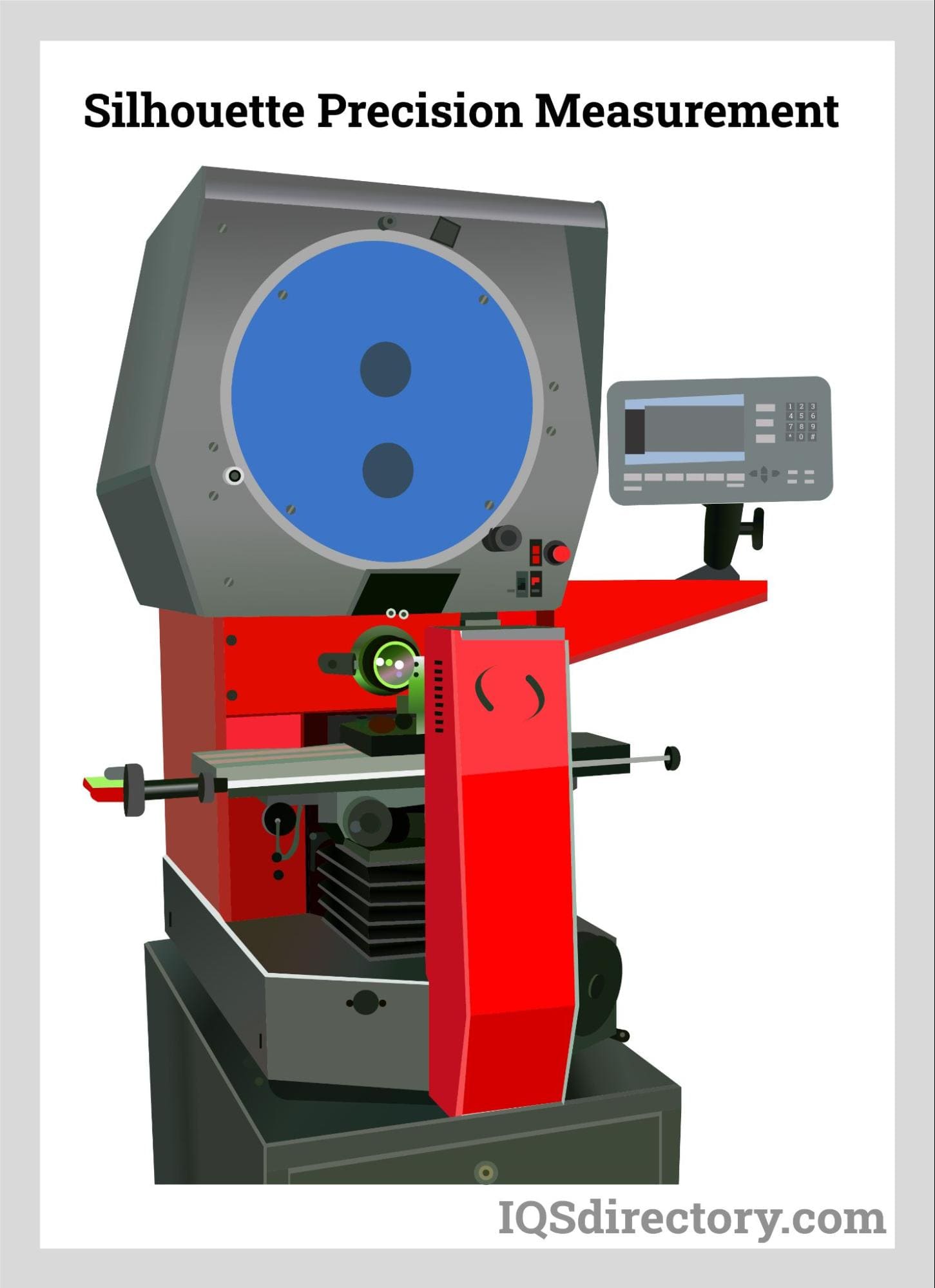
Traditional optical comparators use the outdated silhouette method to observe one part at a time, which is still popular on the market. Digital video comparators manage the entire process electronically in a fraction of the time, produce more accurate data, and can assess large numbers of parts..
The size and magnification of traditional comparator’s projected images differ with optics and screen size affecting measurements. Optical comparators typically have screens that start at 12 inches. As a result of the greater distance needed to produce a larger image without distortion, larger screen sizes are only feasible with larger enclosures.
Digital video comparators have the image of the part being examined displayed on a computer monitor for easy manipulation and study. With automated digital comparators, a camera captures an image of a part as it moves along a production line and electronically compares it to a CAD rendering or part image.
Considerations When Choosing an Optical Comparator
Readout and Software
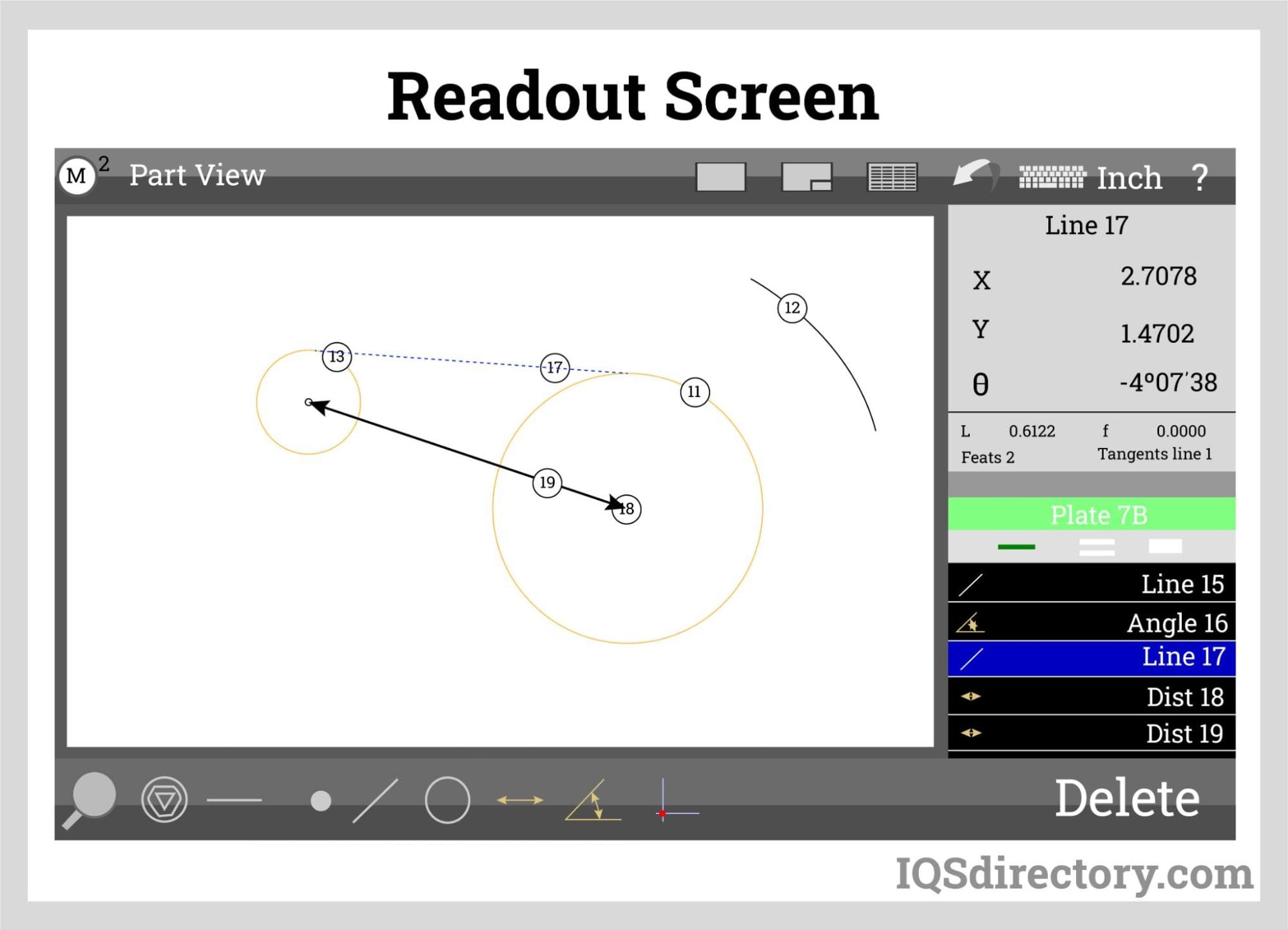
Choose a basic XY digital readout if only fundamental measurements like locations and lengths are needed. However, having geometric capabilities is necessary if the application calls for measuring circles, angles, and parametric distances. If the measurement and inspection are repetitive, CNC-capable readouts should be considered. The optical edge detection method is another important factor. Edge detection removes operator subjectivity and enhances measurement accuracy and repeatability in general.
Options and Tooling
For traditional optical comparators, workpiece should be held firmly to the comparator table to guarantee repeated and precise measurements. To choose a fixture that shows the qualities of their component following the light path that best suits the application, one should be sure to investigate the range of fixtures offered. Today’s choices on the market include rotary fixtures, internal lens turrets, digital protractors, helix stage, corrected images, and LED lighting.
Screen Size
Screen sizes for traditional optical comparators range from 12″ to 32″ One should identify the specific aspects of their program that need to be measured at once before selecting a screen size. When measuring, it might not be possible or required to see the full component. Calculations can be made by dividing the screen diameter by the lens magnification. For instance, a 16″ optical comparator with a 10X lens would allow the user to see 1.6″ of the component on the screen (16″/10 = 1.6″). When viewing a picture with an overlay, many engineers believe that staying within one inch of the screen margin is an excellent practice. Ensure that the stage’s dimensions, weight limit, and capacity will accommodate the components to be measured or inspected.
Optical Comparator Lens Requirement
An operator who is typically alert and focused on the task at hand can consistently discriminate 0.004″ on a comparator screen. One should consider the resolution of the lens’ magnification. One can choose the right lens based on the necessary tolerances. The magnification of the projection lens is constant. Magnifications are frequently adjusted for varied views of measured parts. Although a single lens is often included in a projector’s standard configuration, additional lenses can be utilized if necessary.
Light Path
One must be aware of the ideal light route for their application. For example, a horizontal light beam traverses a stage in instruments with horizontal light paths. Applications include thread form measurement, castings, transmission shafts, and machined components. Instruments with vertical light paths feature a light beam that moves vertically. On a glass plate, parts being examined and/or measured are put. The system’s XY stage has a glass plate, through which the beam passes. Flat parts including stamped parts, gaskets, electronics, and O-rings are best suited for vertical systems.
Camera
There are several types of cameras that are part of a digital video comparator. They combine an optical comparator, digital microscope, and a non-contact inspection measurement system with auto edge detection. Digital video cameras are designed with large scope resolution, various frame rates, easy interfaces, spectral sensitivities, and sensors. They capture the most minute details of an image for easy manipulation and magnification with precision resolution.
When considering the implementation of a digital video comparator, it is important to consider the types of parts to be assessed and how they will be presented. Digital video cameras are capable of measuring parts as they move on a conveyor or individually like a traditional optical comparator. Additionally, the size, volume, and precision that is required has to be considered due to the high accuracy of digital video comparators.
Technical Support
A trustworthy manufacturer will offer online technical assistance. Customers can contact the business if they need help with their goods thanks to support available from anywhere in the world. Customers may be asked to walk them through the issue over the phone, or they may even gain remote access to the system to investigate and fix the problem themselves. Choose a comparator from a company that will take the time to assist in resolving any issues with minimal downtime.

