Digital Video Comparator
Digital video comparators utilize CAD drawings for accurate comparisons, incorporating laser measurement tools and specialized comparison software. The vision system is linked to a computer, which is used to calibrate and adjust the video comparator’s settings for precise measurements.
Light Source
The workpiece is positioned on a glass plate with a light source underneath. This light illuminates the workpiece and is captured by a video camera positioned directly above the glass plate, providing a clear image of the item being measured.
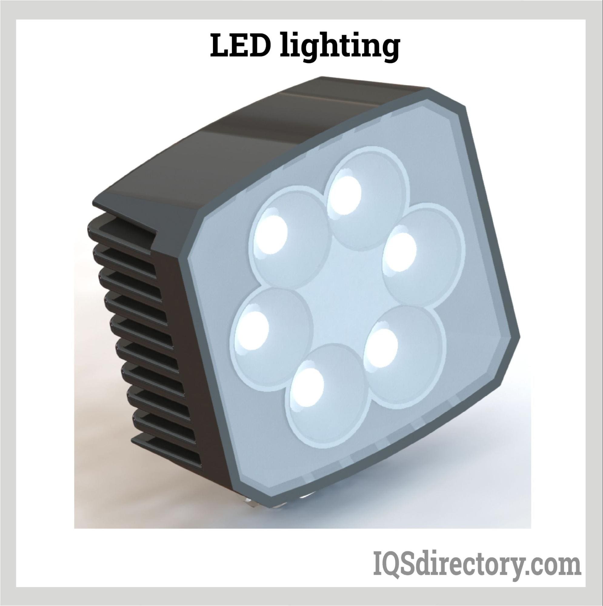
LED Lights
The camera lens is encircled by LED lights, with the quantity varying by manufacturer and model of the comparator system.
Camera
Digital video comparators utilize various types of cameras, with the most common being charge-coupled device (CCD), complementary metal-oxide semiconductor (CMOS), and gigabit ethernet (GigE) cameras.
- Charged Couple Device (CCD) Camera: A CCD camera has a sensor that converts light to digital signals through charges that are created by photons. The captured light is converted into digital signals that are displayed as pixels on a monitor. The process of a CCD camera or sensor includes light to charge conversion, charge to accumulation, charge to transfer, charge to voltage conversion, and signal amplification.
- Complementary Metal-Oxide Semiconductor (Cmos) Camera: CMOS cameras have improved technology that is used to replace CCD sensor cameras. They have an integrated circuit that records an image using millions of pixel sensors that have photodetectors. As an image enters the camera from the lens, the photodetectors get an electrical charge. The charges are changed into a digital reading that measures the strength of the light source and color, which are converted into pixels to be displayed on a monitor.
- Gigabit Ethernet (Gige) Camera: GigE cameras have high resolution and rapid transfer of data at one billion bits per second or 125 million bytes per second. They are capable of capturing complex details and providing precision data. GigE cameras are able to run directly off a computer and examine parts and components as they appear on an assembly line. For a GigE camera to operate successfully, it has to be appropriately set up to match the requirements of the system, have proper software, and be correctly connected.
Computer
The image captured by the camera is displayed on a computer monitor, where the activation of LED lights is controlled. The display format of the captured image varies by the comparator manufacturer. Typically, the computer screen is segmented into sections that can be managed either manually or automatically.
During the initial setup, the lens and glass table knobs are adjusted to achieve proper image focus. A visual slide is used to calibrate and fine-tune the system. The video comparator features X, Y, and Z axes, with each axis’s position shown on the computer screen. The software package includes options for adjusting measurements related to angles, temperature, and dimensions.
In assembly operations, the positions of the items to be inspected are programmed into the computer system. As the items progress along the assembly line, the camera captures their images and compares them to the CAD renderings.
Computer software provides various light controls, segmented into rings and sections of the lighting circle. The specific controls depend on the system and its software. Additionally, the software allows for controlling the type of view needed for examining the workpiece, including side, top, front, or back perspectives.
Traditional Optical Comparator Parts
Condenser Lens
A condenser lens is an essential component in optical devices, responsible for converting divergent light rays from the light source into parallel rays. As a result, condenser lenses are also referred to as “objective lenses.”
Projection Lens
The condenser lens directs parallel light beams towards the reflective mirror, while the projection lens, positioned next to the condenser lens, facilitates this process.
Screen
The screen displays the image of the workpiece being measured.
Base
The base supports the entire setup, including the table.
Plunger
Plungers are metal components used as sensing elements to detect dimensional changes in the workpiece being measured. They operate by reciprocating a pivoting lever based on the workpiece’s inconsistencies. The plunger and a mirror are connected via a lever fixed at a pivot point, with the plunger positioned close to the pivot. This pivoting lever mechanism enhances the plunger’s movemen
Mirror
A mirror in an optical comparator acts as a reflective surface, redirecting light rays from the light source. It is mounted at one end of the pivot lever and rotates around its center.
Work Table
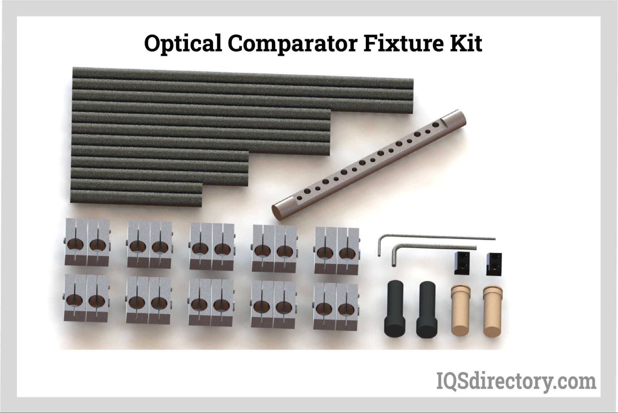
The workpiece to be inspected is placed on a level surface where it is contacted by the plunger. Key considerations include the workpiece’s volume, X and Y travel, and weight capacity. To facilitate easier handling, a precise rotary table, part holder, and other accessories are often used. The comparator should also offer a wide working distance and a versatile, reliable focusing mechanism. With most modern optical measuring projectors now digitized, selecting appropriate data processing options is essential, so consider the system’s data-processing capabilities as well.

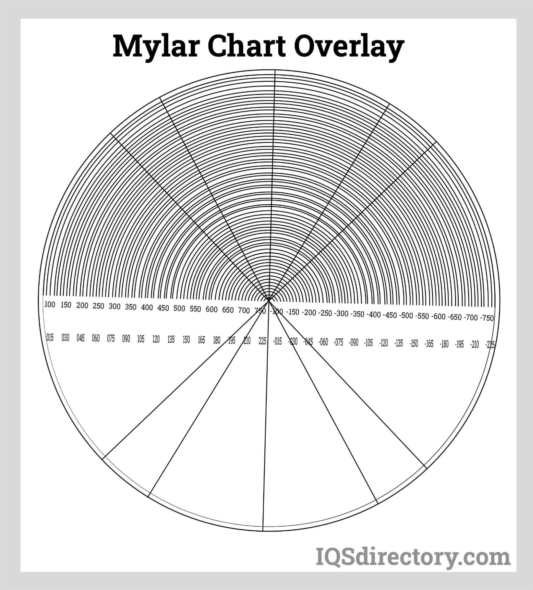
Inset Chart
To use the overlay chart, it must be compared with the projected measurement image on the screen. Various types of charts are available, such as concentric scales or grid patterns. By overlaying the chart on the projected image, you can visualize how the design value contours compare to the actual measurement target, ensuring both are magnified at the same scale.

Surface Lighting
An optical comparator offers two illumination options: epi-illumination from above (the lens side) for projecting outlines, and transmission illumination from below to create shadows. While measuring the target using only the backlit image can be challenging, epi-illumination can still be effectively utilized.

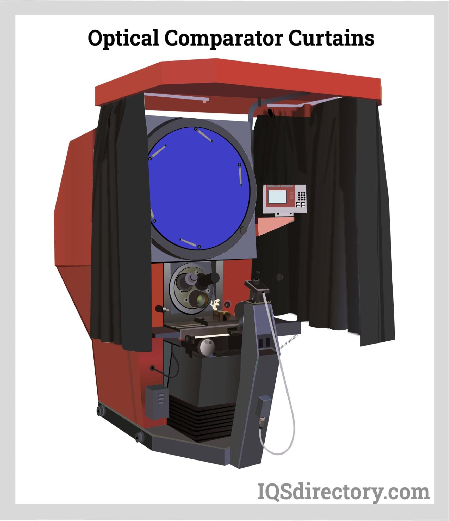
Curtain
Use blackout curtains to block external light and enhance the accuracy of shape depiction by eliminating ambient light interference.

Optical Comparators vs Digital Video Comparators
Since their introduction in the 1920s, visual measurement systems have been integral to industrial and manufacturing processes. Initially, traditional platform systems used silhouettes as reference points for comparisons. With advancements in technology, digital video systems have been developed, offering more accurate and precise measurement data.
Over nearly a century of use, optical comparators have evolved significantly. They can measure small parts along the X, Y, and Z axes using magnification. However, each measurement is taken manually, which can be labor-intensive for operators. Despite lacking computer software and being less advanced, optical comparators are user-friendly and more cost-effective compared to newer technologies.
Digital video comparators utilize computer technology to inspect, measure, and evaluate components, assemblies, and parts individually, in batches, or on a conveyor. Their accuracy, speed, and efficiency make them well-suited for fast-paced modern manufacturing environments. Equipped with zoom optics and precision lighting, these comparators deliver highly accurate measurements and data.
Optical Comparator vs Machine Vision Systems
Both optical comparators and machine vision systems are used to compare, inspect, measure, and identify objects, whether stationary or in motion. Optical comparators focus on visually measuring small two-dimensional parts along the X, Y, and Z axes using magnification, without relying on computer software for the inspection process.
Machine vision systems are automated inspection machines that leverage PC software to conduct inspections swiftly and accurately, with precision up to 0.0002 inch (0.00635 mm). They perform three-dimensional analysis by visualizing and measuring the features of an object.
Optical comparators are limited to 2D and 2½D measurements and do not integrate with computer software or CAD systems. They offer lower optical resolution, reduced throughput, and have limited lighting options, including contour illumination.
Machine vision systems are built on PC software that is easy to use. They are capable of contact measurements and compatible with CAD software. Machine vision systems have high throughput and are able to measure parts that are too small for CMM or parts that cannot be touched. They have larger working distances, fields of vision, and measuring envelopes.


